Example of a sequence built with combinational logicTo illustrate how sequences are built in HER/12 sequencer circuits, we will consider the execution of a simple instruction:
LDR A, B
which causes the content of register B to be copied into register A.
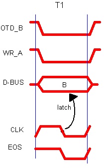
The instruction's exec cycle completes in one clock period (T1), as illustrated in the time diagram below.
First, both OTD_B, WR_A control signals appear simultaneously, causing the content of B to be put in the D_BUS. Register A, however, won't latch until the next falling edge of the clock. This is due to register's design as we discussed previously. With that falling edge we also fire the End Of Sequence signal (EOS).
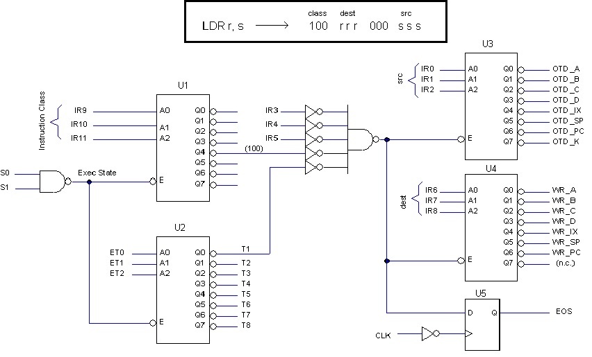
The instruction is encoded in a generic way valid for all registers, as discussed in section "Instruction Set Architecture (ISA)". If bits 11,10,9 (instruction class) are "100" and bits 5,4,3 are "000", then the following circuit will generate the intended sequence; otherwise, none of the output control signals will be activated.
Fist of all, S0,S1 must be "11". Notice in the diagram that all decoders will be inhibited otherwise causing all control signals at the output to be 1 (inactive).
Secondly, the "instruction class" must be "100"; otherwise decoders U3, U4 will be inhibited producing no signal at the output (all ones).
Third, the control signals appear at T1, that is, when E0,E1,E2 = "000".
Finally, bits 5,4,3 must be "000", and this is specific to this instruction in particular.
Decoders U3, U4 decode the appropriate source and target registers directly from the instruction's code. In this case, OTD_B and WR_A would be produced.
The "End of Sequence" (EOS) signal is generated synchronous with the clock by U5..
In fact, this circuit is part of a bigger one. Other sequencer circuits similar to this would be connected to the others U1's outputs, one for each instruction class. Those circuits would take signals T1, T2,... etc, from U2, as appropriate.
This circuit is only an example. Possibly it deserves better design, but it illustrates the following general rules:
* Instruction sequencer circuits inhibit them self is S1,S0 is different from "11" (exec state).
* Different instruction classes select different sequencer circuits.
* The ET count (E0,E1,E2) define different steps within the sequence.
* Fields encoded in the instruction (such as registers) are decoded directly by sequencer's circuitry.
|