Homebrew Mini-Computer based on Z80 CPU |
armandoacostawong@gmail.com |
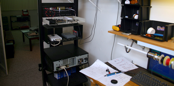
Today I tested the just finished "second-attempt" CPU board. Here are some experiences gained during this test.
Building a single board from two separate drawing is not too comfortable indeed but it's not annoying either. Nevertheless I plan to consolidate both schematics into one but for A3 paper size instead of 11x17. That will be revision 10. Current one is revision 9.
The wiring technique employed proven once again sufficiently flexible for making changes if needed. Even replacing passive components (that I solder directly to the board) resulted not too difficult.
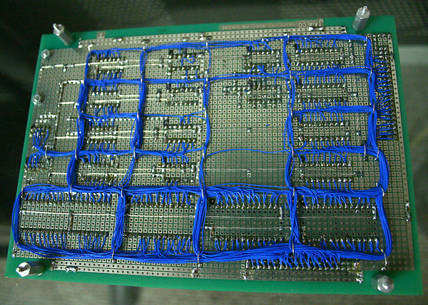
What it seems to be a real problem with this technique is the ordered manner in which wires got accommodated. I’ve started to suspect that it is responsible for the unwanted waveforms I got.
Here is my 4 MHz clock:
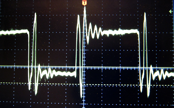
It is supposed to be squared. I suspect that the ondulations found at the edges are due to excessive inductance on the wiring. I don’t suspect on line-termination problems because the wires within the board are too short to “qualify” for transmission lines. Nevertheless this is a matter to be investigated and fixed.
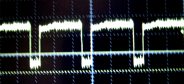
The M1 signal is little more decent:
I’m debouncing my push buttons with the following monostable circuit built with a D-type flip-flop 74ACT74:
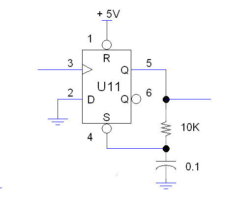
This circuit behaves pretty well. A positive pulse applied to the input (pin 3) triggers a negative pulse at the output which duration depends upon R and C. The good thing is that once the output has started, variation at the input will not affect it, which makes it perfect for button debouncing... if (and only if) R and C have been chosen so the duration of the output pulse is long enough.
The unit (I call it “Master Controller” or MC) wakes up in “Halt Mode” as expected and it goes to that mode each time the reset button is pressed. When I press the Start button, it enters “Run Mode” as it is supposed to. So the Halt Flip Flop (U12) and associated circuits are working fine. Step mode worked fine too.
What’s troubles me is that the “BUS” LED keeps blinking, signaling that the CPU is trying to open the EXT-BUS buffers. I haven’t found anything wrong with the logic; it seems that, simply, the CPU is not running the program from the EPROM as I expect it.
Yes, I burned an EPROM with a simple program that just keeps looping around 0066h. The MC enters “Run Mode” (when I press the Start button) by asserting a NMI interrupt to the microprocessor so it is supposed to branch directly to 0066h where my program is.
This way of “starting” the computer is kind of dirty since nothing have been initialized as, for instance, the Stack Pointer register (SP). I guess that is not too important because the initialization code at 0066h will overwrite whatever random “initialization” that had taken place (as for instance, trying to save the Program Counter (PC) to the “stack” in response to the NMI interrupt).
The thing of the matter is that this and other simple program simply did not run, so something is still wrong. I suspect that wiring mistakes remain unrevealed so my next task is to carefully review it… line by line.