Homebrew Mini-Computer based on Z80 CPU |
armandoacostawong@gmail.com |
-- Sorted in ascendant order (Most recent bottom).
06/16/2016
In the previous post (dated 12/13/2011, labeled: -- Final fix) I described a problem related with "noise" in the EXT-BUS that I "fixed" by removing the buffer IC from the socket. The problem was caused indeed by collision when reading the SAR register but the solution has nothing to do with line termination. What I did was to modify the "Bus Gating" circuit so it takes into account the fact that SAR is being addressed. Now there is no collision because the BUS remains closed when the SAR register (ports 01H and 02H) is being accessed by the Microprocessor (which occurs when the START button is pressed).
06/23/2016
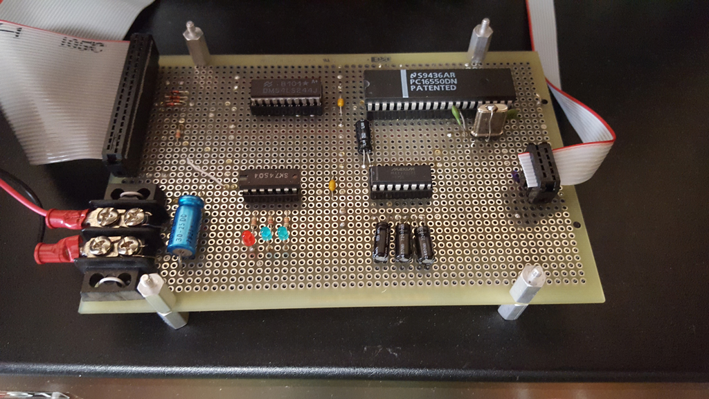
The first step into building peripherals is to test the EXT-BUS to which they will connect. To this end, I built the simplest circuit I could imagine, which is the following:
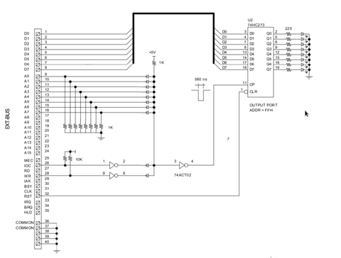
This board provides an output port with address FFH. The data is latched and presented in LEDs. The address decoding circuit is made with diodes for simplicity thought that is not a good solution indeed.
The circuit worked but not before I added pull-up resistors to the control lines (IOC, WR) and pull-down resistors to all Address lines, as shown. Before, noise was all around and behavior were erratic.
The circuit was tested using the following program:
;--------------------------------------------
PORT	.EQU	$FF
DATA	.EQU	$55

	.ORG	$2000
	LD	A, DATA
LOOP
	OUT	(PORT), A
	JP		LOOP
;--------------------------------------------
Data can also be written directly from the Console (as I could verify) but using the loop was very useful for troubleshutting the erratic problems mentioned above.
07/06/2016
Modified the test board to add an input port as shown in the following drawing:
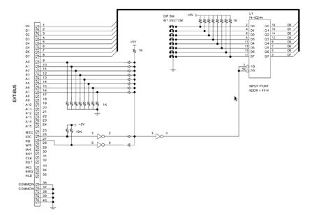
Same address (FFH) but decoding using RD signal instead of WR.
The test was successful: I was able to read the DIP switches from program as well as directly with the Console.
07/08/2016
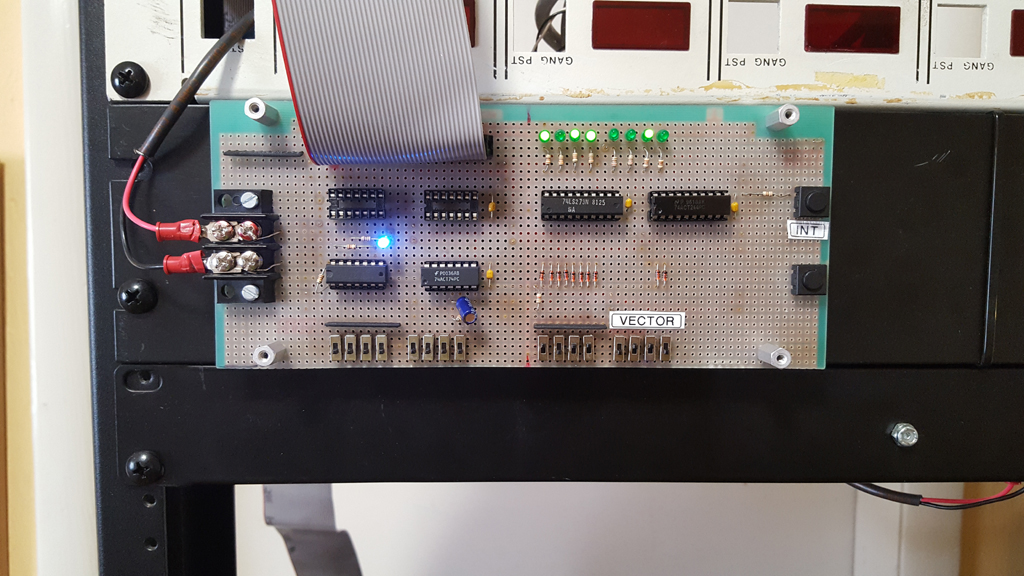
Modified the input port in the test board to act as interrupt vector provider as shown in the drawing below (click to view):
Test board schematicTested using the following program:
;------------------------------------------------------------------
; PROGRAM TO TEST INTERRUPTS MODE 2 USING THE TEST BOARD
;------------------------------------------------------------------

PGM	.EQU $2200	; Program to be interrupted
ISR	.EQU $2300	; Interrupt Service Routine
PORT	.EQU	$FF	; Address of output port
DTA1	.EQU	$F0	; Data written by PGM
DTA2	.EQU	$0F	; Data written by ISR

;------------------------------------------------------------------
; INTERRUPT TABLE
;------------------------------------------------------------------

	.ORG	$2002
	.WORD	ISR

;------------------------------------------------------------------
; MAIN PROGRAM
;------------------------------------------------------------------

	.ORG	PGM

	LD	SP, $6000	; Set Stack Pointer
	LD	A, $20		; Set Interrupts Table address
	LD	I, A
	IM	2		; Set Interrupt Mode 2

	LD	A, DTA1
	OUT	(PORT), A	; Iluminate LEDs in Test board
	EI			; Enable interrupts

LOOP

	JP	LOOP		; Wait to be interrupted

;------------------------------------------------------------------
; INTERRUPT SERVICE ROUTINE
;------------------------------------------------------------------

	.ORG ISR
	LD	A, DTA2
	OUT (PORT), A	; Change LED reading in test board
	EI
	RETI

	.END

;-------------------------------------------------------------------
07/10/2016
Removed the signal CLK (Master Clock) from the EXT-BUS, puting that line (31) to ground. This 4MHz clock in the bus always seamed to me a as bad idea but it has been there for years, until now.
Before making the change, I meatured that pin with the Osciloscope which read a very intense noise even with the bus "closed". The noise, of course, desapeared when I removed the CLK signal from the bus.
The other change has to do with the INT lamp in the Console front. This lamp has been connected so far to the IAK signal to indicate that the CPU is taking care of interrupt requests. In practice, however, it seamed better to me to monitor the incoming IRQ request before the INT switch. Now, the lamp INT indicates that some peripheral is requesting interrupt. If one see that lamp iluminate solid for long, possibly the INT switch is inactive (down) so the interrupt can not gets throught.
07/23/2016
Tests accessing external peripherals thought the EXT-BUS had presented some instability. That is because all BUS buffers open or close at the same time causing all signals (Data, Address, Control) to appear or disappear simultaneously. During an I/O write cycle, for example, the WR signal appears at the same time as the Address and the Data, not giving enough time for them to stabilize in the bus.
To remedy this, I modified the CPU Board to insert a delay of half a clock cycle (125 ns) in the opening of the buffer (74HC244) of the control signals: RD, WR, MEC, IOC. The delay is made by using a Flip-Flop to syncronize the BUS_EN signal with the system clock, as shown below:
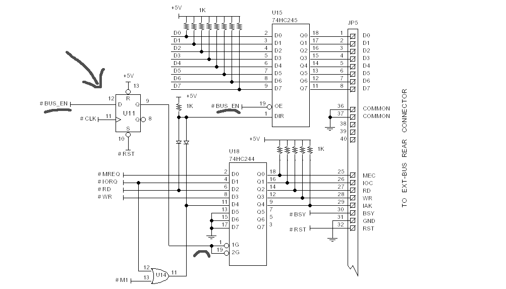
This proved right as the following test succeed when it did not with the previous version.
A test board for testing a serial port based on 16550 UART chip was built, according to the following diagram:
This time I'm using TTL components instead of CMOS. The test today was very simple, just writing a string to the UART one byte at the time in a loop, without FIFO nor hand shaking. I used my MS-DOS computer running KERMIT for Terminal emulation.
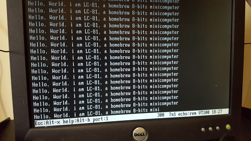
The following program was used.
;------------------------------------------------------------------
; UART TEST BOARD -- SENDING A LONG STRING TO THE TERMINAL
; at 300 Baud using XTAL 4 MHz (no FIFO)
;------------------------------------------------------------------

LINE	.EQU $FB ; Line Control Register
LSTU	.EQU $FD ; Line Status Register
LSB	.EQU $F8 ; Divisor Latch (LSB)
MSB	.EQU $F9 ; Divisor Latch (MSB)
DATA	.EQU $F8 ; Data Register

BDL	.EQU $41 ; divisor for 300 Baud
BDH	.EQU $03

COMM	.EQU 00000011B ; Comm params: 8N1 NP
BUFF	.EQU $4000	; String buffer

	.ORG BUFF
	.TEXT	Hello, World. I am LC-81, a homebrew 8-bits minicomputer
	.BYTE	$0A	; Newline char
	.BYTE	$0D ; Car Return char
	.BYTE	$00	; Null string terminator

	.ORG $2000
	; Set bit 7 in Line Control register
	; to access Divisor Latch Register
	LD	A, $80
	OUT	(LINE), A

	; Set divisor
	LD	A, BDL
	OUT	(LBS)
	LD	A, BDH
	OUT (MSB), A

	; Set comm params
	LD	A, COMM
	OUT	(LINE), A

LOOP

	LD	HL, BUFF

NEXT
NORDY
	; Read Line Status Register
	; check TX-Hold bit (TH) to be 1
	IN	A, (LSTU)
	AND	$20
	JP	Z, NORDY

	;---------------------------------------------
	; Transmit next byte from the buffer
	;---------------------------------------------
	LD	A, (HL)
	AND	$FF		; Check end-or-string (null)
	JP	Z, DONE

	OUT (DATA), A
	INC	HL
	JP	NEXT

DONE

	JP	LOOP

	.END