Homebrew Mini-Computer based on Z80 CPU |
armandoacostawong@gmail.com |
 |
(02/01/2011) The chassis was moved to an industrial rack so it will be easier to add units as they come in the future. |
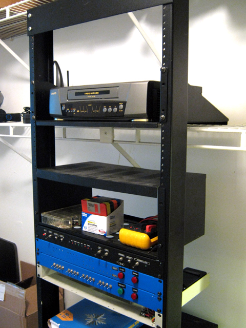 |
For example, the VCR on the top could hopefully become a "tape drive" for the machine. |
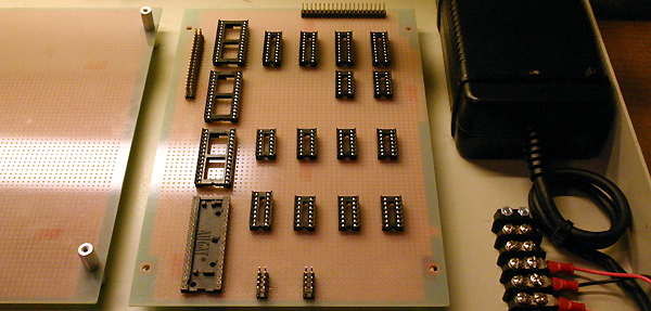 |
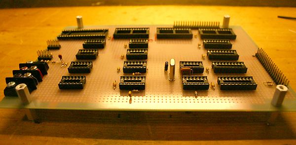
(02/18/2011) Step #1: IC sockets and connectors in place. |
 |
(02/20/2011) Step #2: Power wires (naked). |
 |
(04/04/2011) Step #3: Pasive components. |
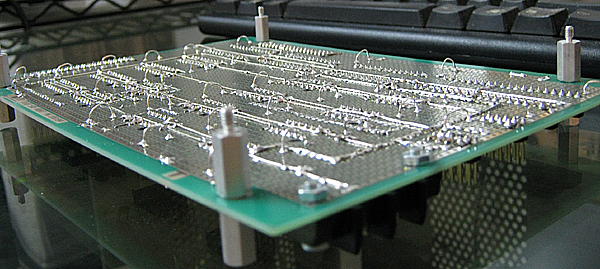 |
(04/04/2011) Step #4: Placed little "half-moons" for guiding wires into ordered hardness (as opposite to "big-mess of wires"). |
 |
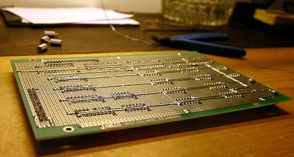
(04/06/2011) Step #5: Start wiring. |
 |
(04/14/2011) Wiring complete (not tested yet) |
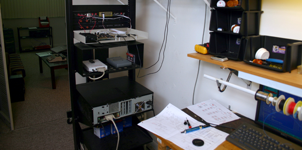 |
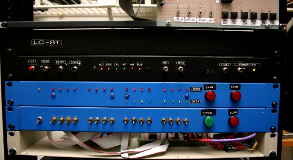
(04/15/2011) Mounted on a open rack with wheels, testing the LC-81 is not too unconfortable. NOTE: The box on the botton is not LC-81 but the MS-DOS PC I use for development. |
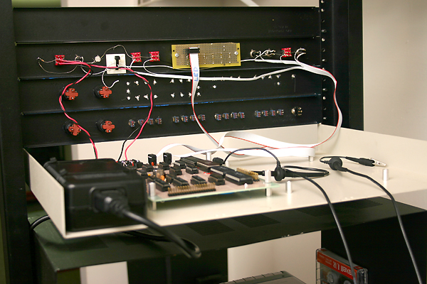 |
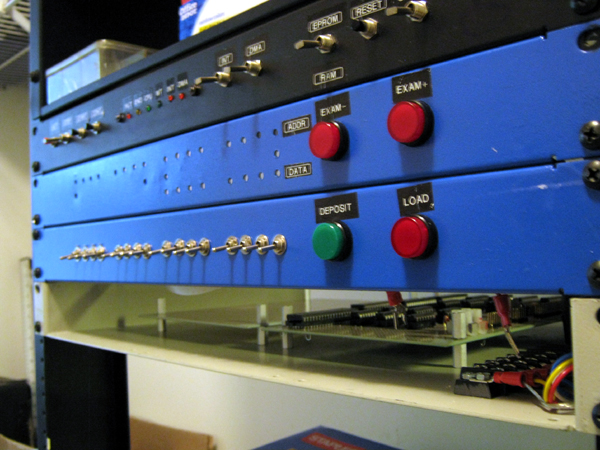
Here is the actual LC-81 "Master Controller" unit (MC), rear view. NOTE: It is not finished. More stuff is pending to put on. |
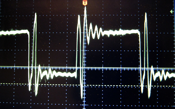 |
Kind of dirty 4 MHz master clock... See also: Testing the CPU Board |
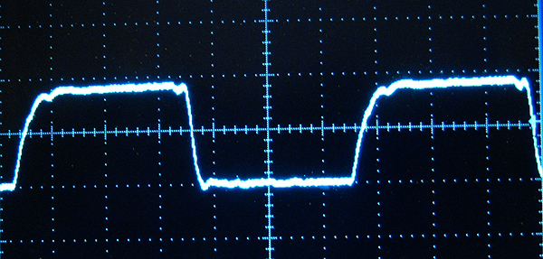 |
(4/16/2011) The problem with my clock's waveform was fixed by replacing U13 (a 74ACT04 chip used in the clock generator) with its TTL counterpart 74LS04. |
 |
(06/03/2011) Display panel, out of the rack, serves as support for wiring the Display boards. |
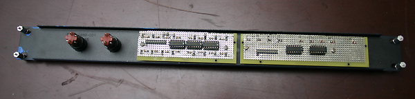 |
The two Display boards mounted on the panel from behind. |
 |
Display-Right board off the panel. |
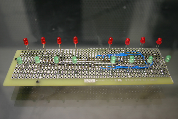 |
Display-Right board bottom being wired (not finished). |
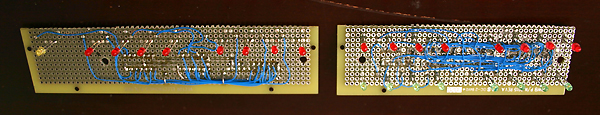 |
Display boards wiring complete. (6/9/2011). |
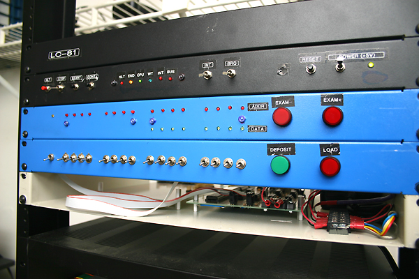 |
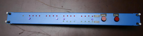
Display finished mounted on the rack. |
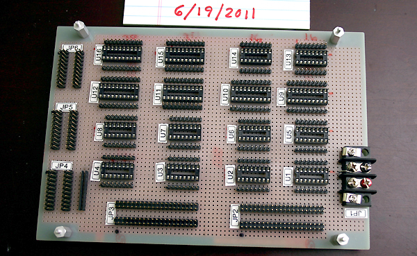 |
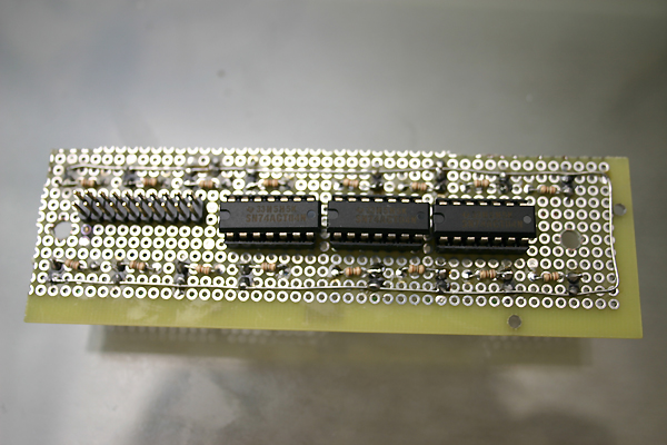
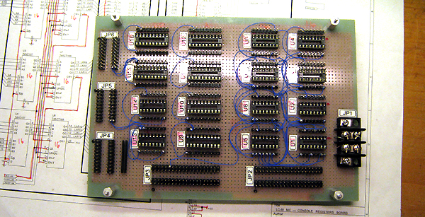
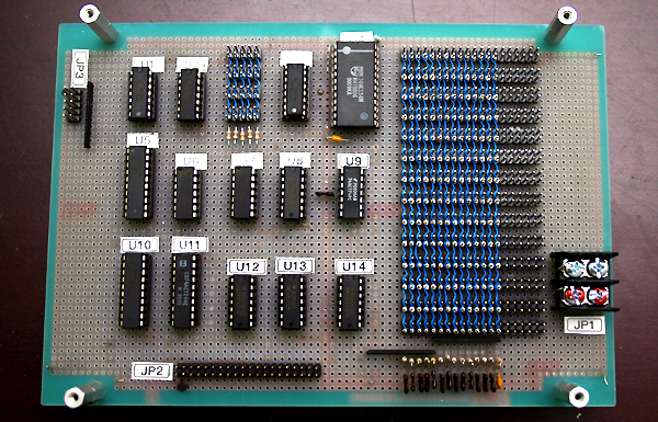
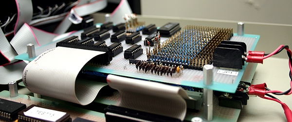
6/19/2011 This board goes wirewrapped (rather than soldered) employing a low-cost technique learnt from the Internet. Step #1: Placing all components on the board. No wires yet. |
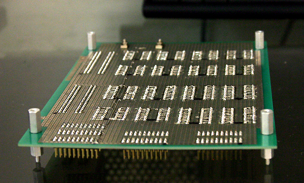 |
6/24/2011 Step #2: Bridging IC sockets to side headers pin-to-pin, using naked wire 30AWG. |
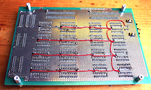 |
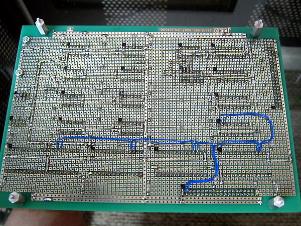
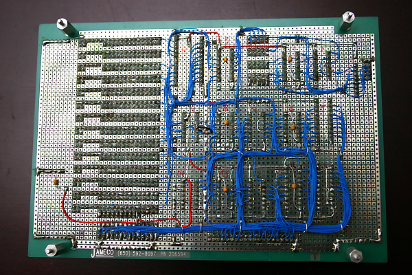
Step #3: Power wires (24AWG) soldered on the lower side. Naked for grounds, insulated for +Vdd. |
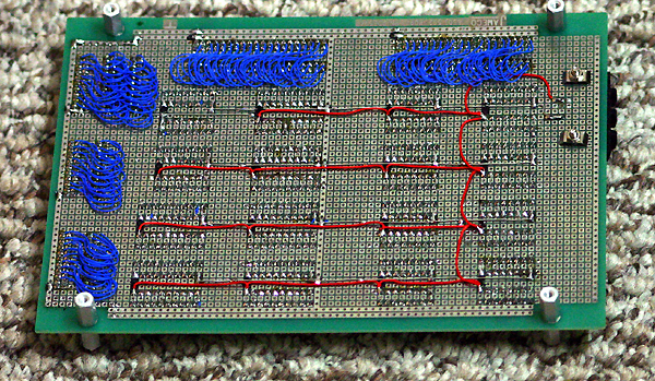 |
Step #4: Bridging connectors to side headers using isolated wires 30AWG. The soldering phase is now complete. Ready for start wirewrapping! |
 |
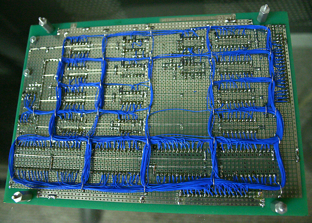
Step #5: Start wire-wrapping (on the components side). |
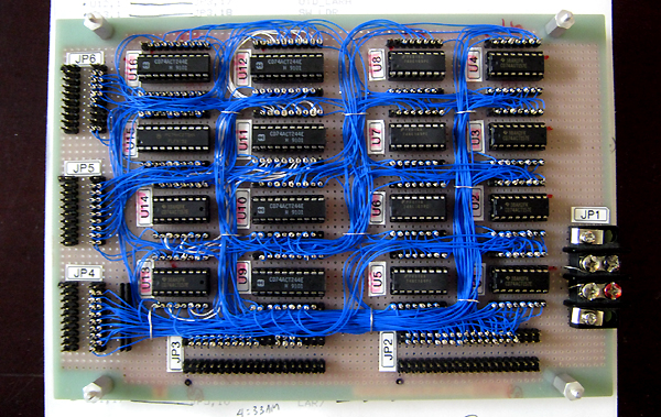 |
Wiring complete. |
 |
The Console Registers board was tested by using an improvised "test board" in place of the (yet to come) Console Controller board. Quite a lot of flaws were found and fixed that way. |
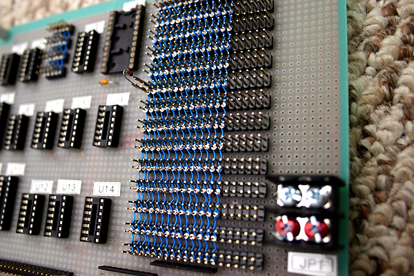 |
Console Controller board in progress. Diodes matrix wiring complete: Rows are soldered in the bottom, columns are wirewrapped on the top. Diodes are plugable for easy "microcode" fix. Only one diode is shown in the picture but it will take about 50. |
  |
Console Controller board finished shown without the (pluggable) diodes. |
|
Console Controller board mounted on top of the Console Registers board. |